One Transaction, Start to Finish
The articles before this one built the pieces separately: what RDMA demands of hardware that a conventional NIC never had to provide (What Is RDMA), the exact byte layout of a RoCEv2 packet (What Is RoCEv2), why that layout carries an IP/UDP header at all (RoCEv1 → RoCEv2), and every operation a Queue Pair can issue, each walked across both hosts on its own page (The Operation Catalog). None of them followed one operation through every stage of the hardware, front to back, or said which part of this book owns each stage. This article does exactly that — one RDMA Write with Immediate, from an application posting a Work Queue Element to the completion landing back in that same application’s Completion Queue — and names, at every stage, which later part of this book owns that stage in depth. Nothing here is explained fully; that’s deliberate. This article is a map, not a chapter.
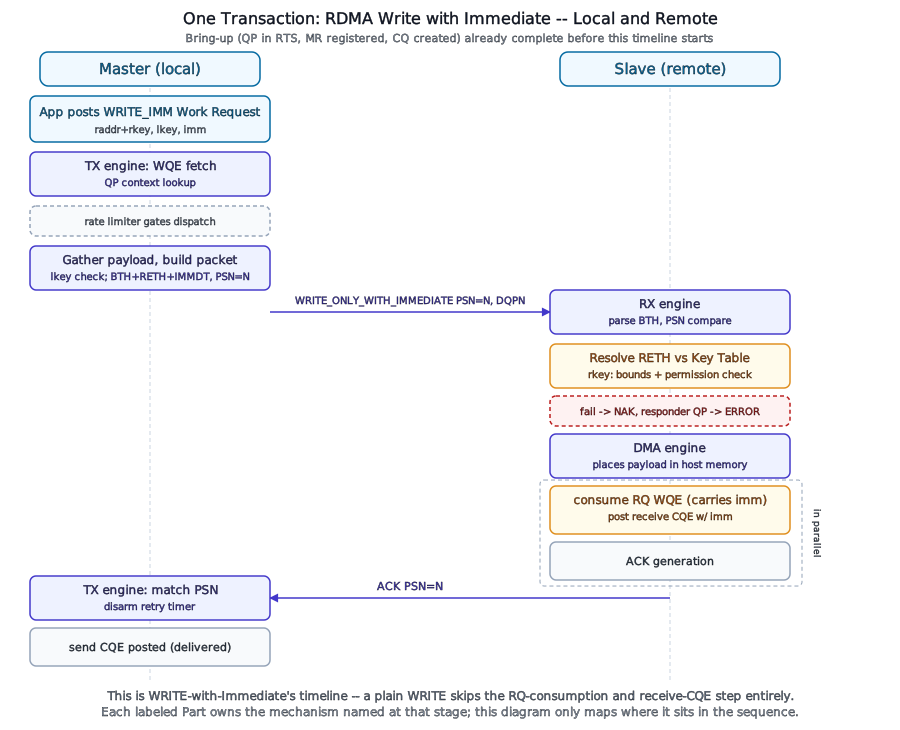
All 12 steps
- Software posts an RDMA Write with Immediate Work Request and rings the doorbell. The request names the local source buffer and its lkey, the remote target address and its rkey, and a 32-bit immediate value. The WQE and the Send Queue Descriptor
- The TX engine fetches the WQE off the Send Queue ring and looks up the sending QP’s context. TX Pipeline
- The rate limiter decides when this QP may dispatch. With no congestion signalled, the gate is open. The Rate Limiter Table
- The lkey is checked against the local Key Table, then the 4,096 source bytes are gathered. The message fits one path MTU, so it becomes a single ONLY packet: BTH, RETH, and ImmDt, with the QP’s next PSN. TX Packet Build
- The packet leaves inside UDP, destination port 4791. The requester records what a resend would need until it is acknowledged, and arms the QP’s retry timer. Retry and Timeout State
- The responder’s RX engine parses BTH. DestQP selects the QP, and PSN 1000 equals the QP’s expected PSN, so the packet is in order. PSN Check and Out-of-Order Arrival
- RETH is resolved against the responder’s Key Table. The rkey must be valid, grant remote write, and cover the whole target range. A failure takes the dashed branch: a NAK, and the responder QP moves to ERROR. Permission and Bounds Violations
- The DMA engine places the 4,096-byte payload in host memory at the target address. The Scatter Path
- Because the operation carries immediate data, the responder consumes the next pre-posted Receive WQE and posts a receive completion carrying the immediate value. A plain RDMA Write skips this step. The ACK already crossing back is the next step. CQE Generation
- In parallel, not after the completion, the responder generates an ACK for PSN 1000 and sends it back to the requester. The AETH’s Message Sequence Number advances to count the completed message. Message Completion and the MSN
- The requester matches the ACK’s PSN against its oldest unacknowledged packet, retires that packet, and disarms the retry timer. Retry and Timeout State
- Only if the Work Request was signaled: The WQE is complete. If the Work Request set its signal flag, the requester posts a send completion to its Completion Queue. CQE Generation
Bring-up: everything that has to exist first
Before any operation can move, four objects have to exist and one handshake has to complete. The application registers a Memory Region against the buffer it intends to write into — pinning the pages and handing the adapter a virtual-to-physical mapping along with an lkey/rkey pair encoding what’s allowed against that memory (owned by Memory Region / Key Table’s Registering a Memory Region). It creates a Completion Queue to receive completion notifications (Completion Queue / Event Management). It creates a Queue Pair and drives it through the hardware-enforced sequence RESET → INIT → RTR → RTS, supplying at each transition the specific attributes that transition requires — destination QP number and path MTU at INIT→RTR, retry count and ACK timeout at RTR→RTS (Queue Pair Management’s Installing a QP and QP State Machine). Only once the QP reports RTS can it send anything at all. Everything that follows assumes this has already happened on both ends of the connection.
The send path: a WQE becomes a packet
The application posts a Work Request describing an RDMA Write with Immediate: a local scatter-gather entry naming the source bytes and their lkey, a remote address and rkey naming where those bytes should land, and a 32-bit immediate value the receiver will see without having to inspect the payload. Posting doesn’t move data — it writes a descriptor into a ring in host memory and rings a doorbell, an architectural producer-index write telling the adapter that new work exists (the exact register-level mechanism is vendor-specific and not part of any public interface; this book describes it functionally). Fetching that descriptor off the ring and managing the ring itself is TX Pipeline’s opening concern (TX Pipeline).
Before the adapter spends any further effort on this WQE, one gate has to pass: Congestion Control Engine’s rate limiter decides whether this QP’s turn to dispatch a packet has actually come, pacing when a WQE proceeds rather than holding a packet that’s already been built — a scheduling-side gate this walkthrough passes through without stopping to examine, since Congestion Control Engine owns what that gate is actually doing.
Once dispatched, the adapter needs the sending QP’s live context — its current PSN, its negotiated path, its state — and getting that context on-chip cheaply, or paying for a miss when it isn’t already cached, is the whole subject of Queue Pair Management’s The QP Table and QP Caching. The adapter also has to validate the local scatter-gather entry against its lkey before it’s allowed to read the source bytes at all — the same Key Table that Memory Region / Key Table spends its first three chapters on, consulted here from the sending side rather than the receiving side.
With permission and context both resolved, the adapter builds the wire packet: a Base Transport Header carrying the opcode, the destination QP, and the PSN drawn from the QP’s live send-sequence state; an RDMA Extended Transport Header carrying the remote address, rkey, and length (present here because this message fits in one packet — a longer message would carry RETH only on its first packet, per The Operation Catalog); the immediate value; and the payload itself, closed out with the invariant CRC described in What Is RoCEv2. Because this is a Reliable Connection operation, the adapter also can’t simply forget the packet once it’s sent: a copy has to be held somewhere until it’s acknowledged, and a retry timer has to start. That holding structure — the replay buffer — and the timer it’s paired with belong entirely to Reliability Engine.
The wire
What actually goes out the port — Ethernet, then IP, then UDP to the fixed RoCEv2 destination port, then the InfiniBand transport headers just assembled, then payload, then ICRC — is exactly the packet What Is RoCEv2 already described field by field. This article doesn’t re-derive it; it just confirms that the packet built above is a real instance of that shape, now in flight.
The adapter is only part of the trip. Here is the same Write with the hosts and the switch drawn in, counting every PCIe crossing on both sides:
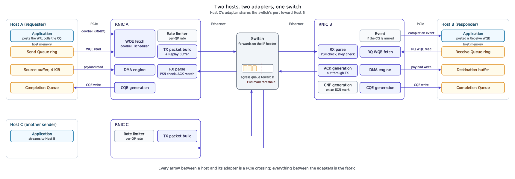
All 16 steps
- On Host A (Requester). The application writes a WQE into the Send Queue ring in its own memory. Nothing has moved toward the adapter yet. The Send Queue Ring
- It rings the doorbell: one 64-byte MMIO write across PCIe, telling RNIC A that new work exists. The Send Queue Ring
- RNIC A reads the WQE back out of host memory, a second PCIe crossing, and looks up the QP’s context. The Send Queue Ring
- The rate limiter lets this QP send. Nothing has signalled congestion. The Rate Limiter Table
- After the lkey check, the DMA engine reads the 4 KiB payload from the source buffer: the third crossing, and the only one carrying the data. The Gather Path
- TX Packet Build puts BTH, RETH and ImmDt in front of the payload, inside UDP, IP and Ethernet, records a Replay Buffer entry, and sends it. TX Packet Build
- The fabric. The switch forwards it on its destination IP address, like any other UDP packet. Nothing in the switch has to understand RDMA. RoCEv1 → RoCEv2
- On Host B (Responder). RNIC B checks the PSN and resolves the rkey for remote write over the whole range. PSN Check and Out-of-Order Arrival
- No. RNIC B’s DMA engine writes the payload straight into the destination buffer across Host B’s PCIe link. The read running beside it is the next step: neither transfer waits for the other. The Scatter Path
- In parallel, because the immediate value needs somewhere to surface, RNIC B reads the Receive WQE that Host B’s application posted earlier. Placement does not need it: the RETH already named the address. The Receive Queue Descriptor and Ring
- CQE Generation writes a receive completion, carrying the immediate value, into Host B’s Completion Queue. It lands behind the payload write, never ahead of it. CQE Generation
- At the same moment, the ACK for PSN 1000 leaves through RNIC B’s own TX path. It does not wait for the completion: the two are separate jobs inside the adapter. Message Completion and the MSN
- Only if software armed the CQ: A completion event tells Host B’s software to look. An application that polls instead finds the CQE on its own. Event and Multi-CQ Arbitration
- The ACK returns (Requester). The switch forwards it back. RNIC A matches it against the Replay Buffer, retires the entry, and disarms the retry timer. Retry and Timeout State
- Only if the Work Request was signaled: RNIC A writes the send completion into Host A’s Completion Queue. CQE Generation
- None. The CQ sits in host memory, so the poll is an ordinary memory read. The whole Write crossed PCIe four times on Host A and three or four times on Host B, and neither CPU copied a byte. The Completion Queue
The receive path: a packet becomes bytes in memory
On the far side, the RX pipeline (RX Pipeline) parses the Ethernet, IP, UDP, and BTH layers off the wire and reads the destination QP number out of the BTH — which drives the same kind of QP Table/Cache lookup Queue Pair Management covers, now performed on the receiving QP instead of the sending one. RX Pipeline also owns a decision this walkthrough deliberately doesn’t resolve: exactly where in the pipeline the incoming PSN gets compared against that QP’s next-expected PSN, and what happens to a packet that arrives out of order. Assume, for this walkthrough, that the packet arrives in order and the check passes.
With the packet accepted, its RETH is resolved against the receiver’s Key Table: the rkey has to map to a valid Memory Region, the requested write has to fall within that region’s registered bounds, and the region’s permission bits have to allow a remote write at all — three separate ways this step can fail, each owned by Memory Region / Key Table’s Permission and Bounds Violations. Only once all three pass does the DMA Engine translate the target virtual address and actually place the payload in host memory, walking a scatter-gather descriptor chain if the destination region isn’t backed by physically contiguous pages.
Because this operation carries an immediate value, it does something a plain RDMA Write does not: it consumes a Receive Request the application posted in advance on its receive queue, and it generates a receive-side completion carrying that immediate value — the application learns data arrived, and what the sender wanted it to know about that arrival, without having posted any work request that names the write itself. Generating that completion, and everything about how a Completion Queue holds and reports it, is Completion Queue / Event Management’s entire subject.
The acknowledgment closes the loop
A Reliable Connection can’t leave the sender in the dark. The receiver owes an acknowledgment, a Base Transport Header plus an ACK Extended Transport Header carrying a syndrome byte and a message sequence number, built and sent back the same way any other packet is — through the same TX path this walkthrough already crossed once, just carrying no payload. When that ACK reaches the original sender, two separate things happen, not one: the reliability engine (Reliability Engine, again) matches it against the outstanding replay-buffer entry by PSN, retires that entry, and disarms the retry timer that was armed when the packet first went out — and, separately, the acknowledgment’s message sequence number tells the sender’s own Work Request logic that this specific operation is done, which is what actually lets a send-side completion land in the sender’s own Completion Queue if the application asked to be signaled for it (Completion Queue / Event Management, once more) — the last event in the sequence, and the one the application was actually waiting to observe.
What just happened, seen from above
One operation, and the QP Table/Cache pattern from Queue Pair Management got consulted twice — once on each end. The Key Table from Memory Region / Key Table got consulted twice as well, once to validate a local read and once to validate a remote write, by two different pieces of hardware on two different machines. The replay buffer from Reliability Engine held state for the entire round trip and nothing else in this walkthrough held state anywhere near that long. That’s not a coincidence specific to RDMA Write — it’s the same storage-structure-plus-working-set shape showing up in more than one place in this single transaction, and it shows up again, differently dressed, in several of the parts this walkthrough only named in passing. The next article names that shape directly, so the rest of this book reads as a pattern applied repeatedly rather than eight unrelated subsystems that happen to sit next to each other on the same die.
The same transaction, followed block by block across the master diagram – each step links to the chapter that owns it:
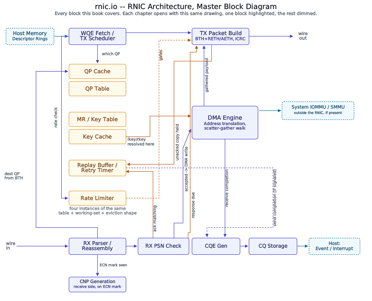
All 18 steps
- Send path (Requester). The doorbell says new work exists. WQE Fetch reads the RDMA Write with Immediate WQE off the Send Queue ring in host memory. The Send Queue Ring
- The scheduler looks up the sending QP’s context: state, next PSN, path. A QP Cache hit avoids a trip to the backing QP Table. QP Caching
- The Rate Limiter checks this QP’s entry. No congestion has been signalled, so the gate opens. The Rate Limiter Table
- The WQE’s lkey resolves through the Key Cache, giving the DMA Engine a validated translation for the source buffer. Key Caching
- The DMA Engine gathers the 4,096 source bytes, through the system IOMMU when one is present, and hands them to TX Packet Build. The Gather Path
- As the packet leaves, the Replay Buffer records what a resend would need: the header fields and a reference to the source buffer, not a copy of the payload. The retry timer starts. The Replay Buffer
- BTH, RETH, ImmDt, payload, and ICRC leave as one RoCEv2 packet, in the same moment its Replay Buffer entry is written. TX Packet Build
- Receive path (Responder). Now on the other machine’s adapter. RX Parser reads the opcode: one packet, carrying both RETH and ImmDt. RX Packet Parse
- DestQP 0x000012 selects the responder’s QP. Its context, including the expected PSN, comes from the QP Cache. QP Caching
- PSN 1000 equals the expected PSN, so the packet is accepted. PSN Check and Out-of-Order Arrival
- The rkey resolves through the Key Cache and must grant remote write over the whole target range. Then the DMA Engine places the payload, through the system IOMMU when one is present. The Scatter Path
- Immediate data consumes a pre-posted Receive WQE, so CQE Generation writes a receive completion carrying the immediate value into CQ Storage. A plain WRITE produces no completion on the responder. The ACK leaving beside it is the next step. CQE Generation
- At the same time, RX PSN Check tells the responder’s own TX Packet Build that a response is due, and the ACK for PSN 1000 goes out; it does not wait for the completion. The AETH’s MSN counts the completed message. Response Generation
- Only if software armed the CQ: The new entry raises a completion event to the host. Event and Multi-CQ Arbitration
- The ACK returns (Requester). Back on the requester. RX Parser hands the ACK to PSN Check, which matches it against the outstanding packets. PSN Check and Out-of-Order Arrival
- ACK matching retires the Replay Buffer entry for PSN 1000 and disarms the retry timer. Nothing will be resent. Retry and Timeout State
- Only if the Work Request was signaled: The MSN covers the WQE, so it retires, and CQE Generation writes a send completion into the requester’s CQ Storage. Message Completion and the MSN
- Recap. Every block this one WRITE touched, marked by which machine used it. Nine did work on both machines. The Replay Buffer is the one that held state across the whole round trip.
Food for Thought
This walkthrough touched the QP Table/Cache pattern (Queue Pair Management) and the Key Table (Memory Region / Key Table) without dwelling on either, and named the replay buffer (Reliability Engine) as the structure holding state for the entire round trip. Before reading the next article’s own reveal: based only on what this one transaction actually touched, which other parts of this book are likely to face the same table-plus-working-set-plus-eviction question?
References
- InfiniBand Trade Association, InfiniBand™ Architecture Specification, Volume 1 (General Specifications).
- InfiniBand Trade Association, Supplement to InfiniBand Architecture Specification Volume 1, Release 1.2.1, Annex A17: RoCEv2 (2014).
- J. Postel, Internet Protocol, RFC 791, IETF (September 1981).
- J. Postel, User Datagram Protocol, RFC 768, IETF (August 1980).
- Internet Assigned Numbers Authority, Service Name and Transport Protocol Port Number Registry (UDP port 4791, “roce”).