Key Caching
Overview
Every DMA the adapter issues against a memory region – an incoming RDMA Write resolving an rkey, an outgoing operation resolving an lkey – needs a translated physical address before the transfer can happen. Resolving that translation from the MR/Key Table’s backing store on every DMA would put a DRAM or PCIe round trip on the critical path of every transfer, the same problem QP Caching already described for QP context. The Key Cache exists for the same reason the QP Cache does: to make a translation that’s actively in use resolve on-chip, and to make one that isn’t cost a measurable, bounded penalty. What this chapter adds that Queue Pair Management’s version didn’t need to say explicitly: the SRAM doing that job for MTT/MPT is the identical SRAM doing it for QP context, and the two working sets are drawing from one shared, finite pool, not two separately sized ones.
Locator
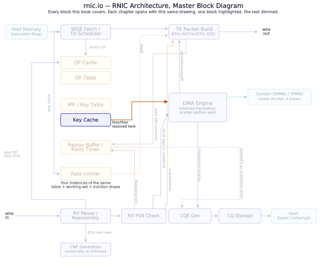
The Key Cache is the on-chip working set of MPT/MTT entries sitting in front of the MR/Key Table’s DRAM/HBM-backed storage – this chapter, in the master diagram above. It is drawn as its own box for the same reason QP Caching drew the QP Cache as its own box: each is the working set for a different structure’s lookups. But the two boxes are not two pieces of silicon. They are the same SRAM.
Block diagram
All 8 steps
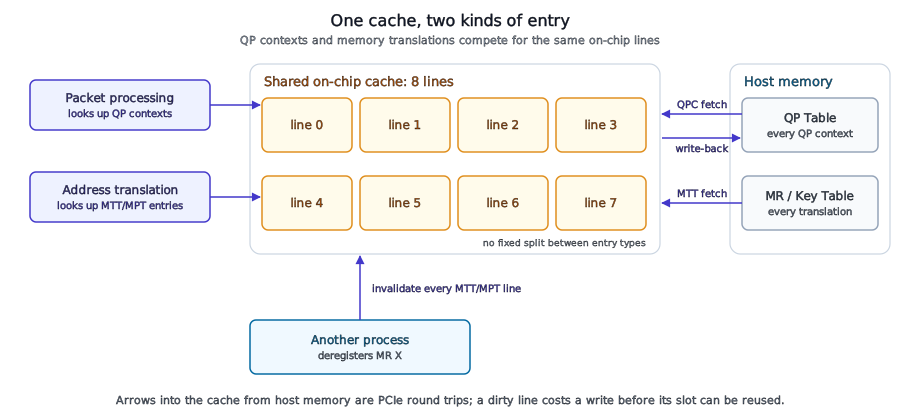
- Capacity pressure. The cache is full and warm. QP contexts and MTT/MPT translations sit in whatever line was free when they arrived; nothing reserves lines for either kind. QP 2 sent a packet a while ago and its next PSN moved on-chip, so line 2 is dirty: newer than the QP Table’s copy. Key Caching
- A packet arrives for QP 5. Its context isn’t in any line: a miss. QP Caching
- Yes. The victim is chosen by recency, not by type, so QP 5’s context replaces MTT D in line 7. A translation is never modified on-chip, so dropping it costs no write. Eviction Policy
- A DMA now needs memory region D. Its translation was the line just given to QP 5: a miss caused by QP traffic, not by memory-region traffic. Key Caching
- The next victim is QP 2’s context, and it is dirty. Its line can’t be reused until the newer copy is written back to the QP Table, or QP 2’s progress would be lost. Eviction Policy
- Only then is MTT D fetched into line 2. One translation miss cost two PCIe crossings: a write and a read. Key Caching
- Deregistration. Every MTT/MPT line. Kong et al. (NSDI 2023) attribute what they measured to deregistration invalidating the whole translation cache, not just the departing MR’s entries. QP contexts stay. Key Cache Eviction Policy
- The victim’s next DMAs miss on translations it used a moment ago, and each one is a PCIe round trip to the MR/Key Table. On a ConnectX-5, a neighbour deregistering MRs roughly tripled a victim’s MTT miss rate and collapsed its throughput; a neighbour only registering MRs barely moved either. Key Cache Eviction Policy
Deep walkthrough
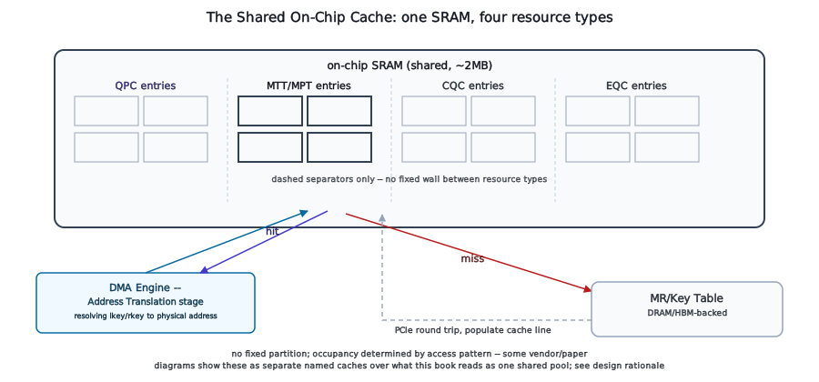
What. The uRDMA paper’s cache model states this plainly, describing the RNIC processing unit’s relationship to its own on-chip cache: “the RNIC PU directly interacts with the cache to query QP context metadata and memory region information from QP Context table and Memory Translation/protection Table (MTT) respectively… cache also needs to maintain other essential metadata, including Completion Queue Context (CQC) and Event Queue Context (EQC).” Four resource types, one cache, straight from this paper’s own architecture description – not an inference this book is drawing from a QP-side source, since QP Caching is explicit that it has no citable SRAM-size or partitioning finding of its own to extend here. No source found gives MTT/MPT a separate capacity number, and none should be assumed: this is evidence of one shared, unpartitioned pool serving QPC/MTT/MPT/CQC/EQC together, not a claim about total SRAM size.
Kong et al.’s own architecture description (NSDI 2023) complicates that picture: it names an ICM cache, a WQE cache, and MTT/MPT as if they were separate structures, not explicitly one undivided pool the way this chapter frames it. That may be a schematic simplification – naming logical categories the paper measures independently, over a physical SRAM budget that’s still shared – rather than a real contradiction of the “one pool” claim above, but no source this book found reconciles the two framings explicitly, so treat “shared, unpartitioned SRAM” as this book’s best-supported reading, not a fact every source states identically.
Where this is checked. The DMA Engine’s Address Translation stage is where a physical address actually gets resolved from a key. The master diagram inventory names this same stage as where Memory Region / Key Table’s Key Cache actually gets consulted – reached whenever an RDMA operation’s lkey or rkey needs to become a real address before a transfer can proceed. This chapter stops at the cache lookup itself; the actual page-walk and scatter-gather mechanics that run once a translation is in hand belong to DMA Engine, forward-referenced here rather than re-derived.
When it fails. A translation that isn’t cache-resident costs a PCIe round trip to the backing MR/Key Table before the DMA it’s gating can proceed – the same order-of-magnitude penalty QP Caching already established for a QP-context miss, and for the identical underlying reason: DRAM/PCIe latency in place of on-chip SRAM latency. Because the cache is shared rather than partitioned by resource type, this cost isn’t confined to MR-heavy workloads specifically – a workload that actively touches enough distinct memory regions to exceed the shared working set pays it regardless of how few QPs it’s using, the same way a QP-heavy workload can push MTT/MPT entries out of that identical SRAM. Kong et al. (NSDI 2023) and the uRDMA paper both document this exact cross-resource contention directly, on real hardware – not a theoretical risk this book is reasoning toward on its own.
What happens next. Because this cache is shared, not partitioned, pressure doesn’t stay contained to whichever resource type caused it. A QP-heavy workload that pushes QP Caching’s working set past its own comfortable size isn’t only generating QPC misses – it’s evicting MTT/MPT entries out of the exact same SRAM those QP contexts live in, and the reverse holds equally: a large registered-MR population competing for space can push active QP contexts out, degrading packet processing that has nothing to do with the memory region driving the eviction. What decides which entry gets evicted, from which resource type, under this shared pressure is Key Cache Eviction Policy and Hardware-Assisted Key Cache Eviction’s subject; this chapter’s job is establishing that the pressure is real and cross-resource, confirmed on shipped hardware, not a corner case invented for the sake of completeness.
Gotcha
A QP-heavy workload degrading unrelated memory-region lookups (or the reverse) isn’t a bug – it’s the direct, confirmed consequence of one shared, unpartitioned SRAM pool. Don’t assume MTT/MPT misses only correlate with memory-region-heavy traffic; a QP population alone can push translations out of the same cache.
Why
A dedicated, fixed slice of on-chip SRAM for each of QPC, MTT/MPT, CQC, and EQC is an available alternative to sharing – simpler to reason about, and no resource type can ever be starved by another’s workload. The tested hardware this chapter’s evidence comes from doesn’t do that: it shares one pool across all four instead, the same tradeoff any cache faces when deciding whether to partition by data type – a fixed split wastes SRAM on whichever resource type a given deployment happens to use lightly, while starving the one it uses heavily, and the right ratio is workload-dependent in a way no single silicon design fixed at tape-out can adapt to. Sharing the pool lets the cache’s occupancy follow the actual access pattern instead of a static guess, at the cost this chapter already named: a workload heavy in one resource type can degrade a completely unrelated one sharing the same SRAM. Whether a different real design partitions instead, and eats the opposite cost, isn’t something this chapter can rule out – only the shared-pool tradeoff is the one this chapter’s evidence actually speaks to.
Registering a Memory Region covers what happens before any of this: how a memory region gets into the table – and, for one entry at a time, into this cache – in the first place.
References
- No IETF or IBTA standard governs on-chip MTT/MPT caching and working-set sizing – it is implementation-specific silicon design, not a wire-format or software-interface contract any standards body defines. This chapter’s treatment is grounded in the sources cited in-text above, not a standards document.