The Rate Limiter Table
Overview
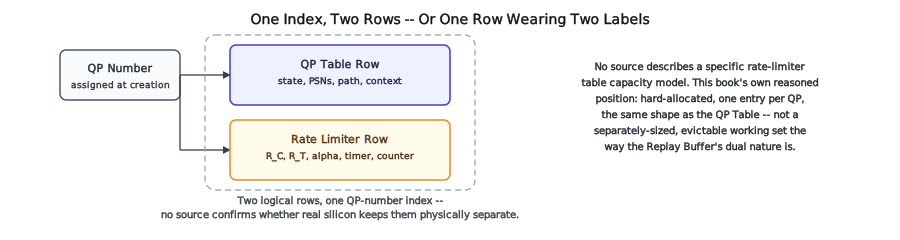
Every field the previous chapter named lives in exactly one place per QP: an entry addressed the same way The QP Table’s own entries are, by the QP number assigned once at creation and held fixed for that QP’s life. This chapter covers that addressing in full, resolves an open question from QP Capacity and Timing about what kind of resource this actually is, and names a real possibility this book can’t rule out: that “the Rate Limiter Table” isn’t a separate structure from the QP Table at all.
Locator
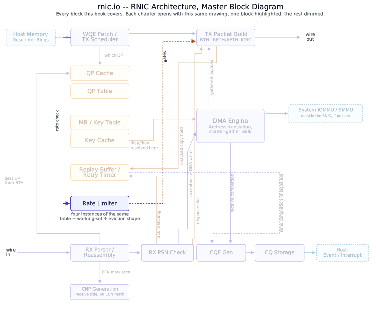
Rate-Limiter Context covered what’s inside one entry. This chapter is about how a QP number finds the right one, and what kind of resource this actually is.
Block diagram
Deep walkthrough
Addressed by QP number – reasoned from wire-level evidence, not directly confirmed. The DCQCN paper addresses rate-limiter state by “flow,” and doesn’t define what a flow is for an IP-routed deployment beyond the IP five-tuple. RoCEv1 → RoCEv2 already established the piece that closes this gap: RoCEv2’s UDP source port “carries no real port semantics at all,” existing purely to vary ECMP entropy between connections sharing an endpoint pair – which only does useful work if two QPs between the same pair of hosts get different source ports. That’s consistent with one rate-limiter entry per QP, the same granularity The QP Table already uses, though no source states this as a direct fact the way The Completion Queue could cite a real interface’s own documentation for CQ addressing. Treat this as this book’s own reasoned inference, not a settled fact.
This reasoning is scoped to RC/UC specifically, the same way this book’s own transport scope generally is – it assumes one fixed peer per QP, set once at INIT→RTR. A UD QP has no such fixed peer at all: QP Context already established that a UD QP “names its destination per-message rather than once at connection setup,” with “no destination-QP field even.” Whether or how UD traffic’s congestion state is tracked per-QP, per-destination, or some other granularity entirely is a question this chapter’s argument doesn’t reach and doesn’t claim to.
Gotcha
Don’t confuse “addressed the same way as the QP Table” with “the same size range.” A rate limiter’s entry count is still bounded by however many QPs an implementation supports concurrently – it doesn’t get its own, independently-sized capacity limit the way The Replay Buffer does.
Resolving QP Capacity and Timing’s open question – hard-allocated, not dual-natured. That chapter left open whether a Rate Limiter entry behaves like the QP Table’s hard-allocated row, reserved whether or not the QP is doing anything right now, or like the Replay Buffer’s dual nature, a hard logical quota with a separately-sized, evictable on-chip working set. Rate-Limiter Context already noted that the DCQCN paper describes this state as living “on the NIC die” per flow, with no cache-versus-backing-store split described anywhere. That points toward the QP Table’s shape, not the Replay Buffer’s: one entry, reserved for the QP’s whole life, not a small working set backed by a much larger logical allocation elsewhere. Caching, next, treats this honestly as this book’s own reasoned position rather than a confirmed fourth instance of a pattern this book has already sourced elsewhere.
A real possibility this book can’t rule out: this may not be a separate table at all. Every field in this Part’s own Context chapter is small – two rates, one reaction factor, a timer, a byte counter, and two stage counts – and every one of them is addressed by the exact same QP number The QP Table’s own entries already use. Nothing about that requires a second, independent storage structure sitting elsewhere in the adapter: a real implementation could just as easily extend each QP Table row with these additional fields directly, the same physical entry serving both purposes. This book draws “Rate Limiter” as its own box, the same way the master diagram does, because it’s a cleaner way to teach the mechanism in isolation – not because any source confirms real silicon keeps it physically separate from QP context.
Analogy
This is the same physical-versus-logical distinction Key Caching already drew for a different pair of resources: QPC and MTT/MPT are logically distinct, covered in separate chapters, while a real implementation’s own architecture description places both in the identical shared on-chip SRAM. Whether Rate Limiter state sits in that same shared pool, in QP Table’s own row, or somewhere else entirely is not something any source this book found actually settles.
Where this gets checked. One place asks this table a question, unlike The QP Table’s two: the TX side, at the point Rate-Limiter Context already named – before a scheduled WQE is allowed to proceed toward becoming a packet. There’s no RX-side lookup against this specific table the way an arriving packet’s destination QP number drives a QP Table lookup on receipt; the RX side’s own relationship to congestion control is CNP Generation’s subject, not a lookup against this structure.
What happens when a lookup doesn’t resolve. A QP that exists but was never enabled for congestion control is not the same failure shape as The QP Table’s unallocated-index case – there’s no malformed or stale packet involved, just a QP that isn’t opted into rate limiting at all. Whether such a QP has no entry, a disabled-by-default entry, or is simply exempted from the rate-check gate entirely is a question this chapter defers to Enabling Congestion Control, which covers the software-to-hardware handoff this table’s entries actually come from.
What this table is not. Its job, on either the shape this chapter settles on, is holding this Part’s own five fields, addressed by QP number. It has nothing to do with whether a CNP has actually arrived recently – that’s Rate-Limiter Context’s own field, already covered, not a separate lookup structure of its own.
References
- No IETF or IBTA standard governs Rate Limiter table storage or addressing – it is implementation-specific silicon design, not a wire-format contract any standards body defines. The per-QP addressing argument above is this book’s own inference from RoCEv1 → RoCEv2’s already-sourced UDP-source-port discussion, not a direct citation for this table specifically.
- Zhu, Eran, Firestone, Guo, Lipshteyn, Liron, Padhye, Raindel, Haj Yahia, Zhang, “Congestion Control for Large-Scale RDMA Deployments,” SIGCOMM 2015 – the “maintained on the NIC die” per-flow framing this chapter’s hard-allocated conclusion rests on.