Replay Buffer Caching
Overview
QP Caching and Key Caching both established the same fact for two different resources: a real adapter’s on-chip SRAM is small, shared, and expensive, and every structure with a working set larger than what fits on-chip pays a measurable cost when it doesn’t fit. The Replay Buffer is a third instance of exactly that question, with one wrinkle the other two don’t share – its working set isn’t shaped by how many distinct QPs or memory regions a workload happens to touch, but by how long an entry has to survive before an acknowledgment retires it.
Locator
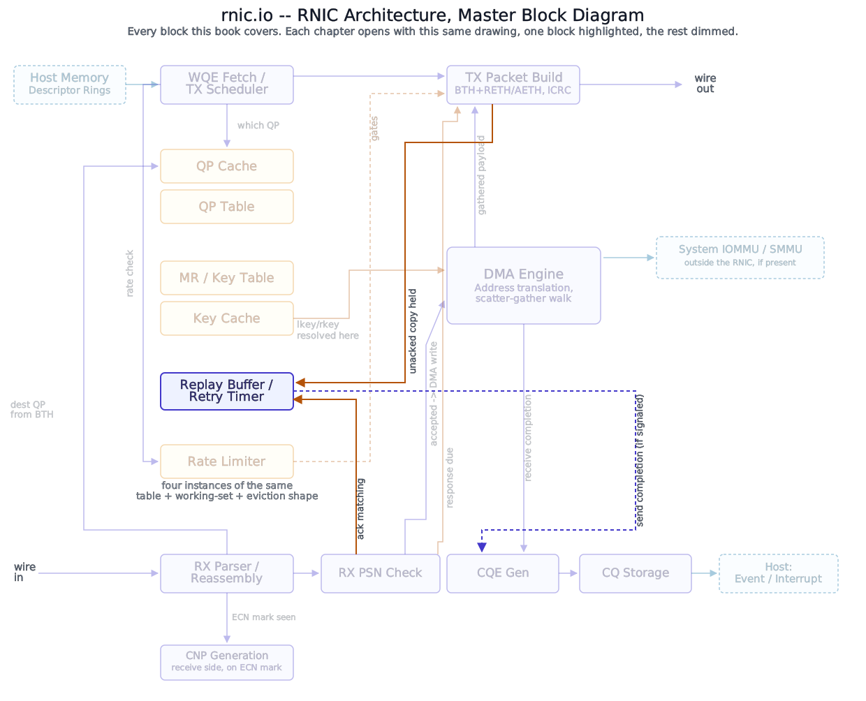
The Replay Buffer covered what this structure holds and how it’s addressed. This chapter covers where it actually lives while a QP’s outstanding requests wait on acknowledgment.
Block diagram
Deep walkthrough
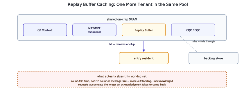
The same shared pool, one more competitor. Key Caching already established that a real adapter’s on-chip SRAM is not partitioned by resource type – QP context, address translations, and (by the same reasoning this chapter extends) Replay Buffer entries are all real candidates to share one physical pool rather than each getting a dedicated, fixed slice. A workload that pushes hard on one resource type can degrade a completely unrelated one sharing the same SRAM, the exact cross-resource contention Key Caching already walked through in depth for QP context against address translations. Nothing about the Replay Buffer’s own nature exempts it from that same pressure.
What actually determines this working set’s size, and why it’s not like the other two. A QP Cache’s working set is shaped by how many distinct QPs are actively carrying traffic; a Key Cache’s is shaped by how many distinct memory regions are actively being touched. Both are, roughly, a function of how much a workload has open at once. A Replay Buffer’s working set is shaped by something else entirely: not how many QPs exist, but how many packets each one currently has outstanding and unacknowledged – which is itself a function of round-trip time. A connection to a nearby peer with fast, frequent acknowledgments keeps very little replay state resident at any moment, because entries retire almost as quickly as they’re created. A connection to a distant peer, or one whose acknowledgments arrive in batches rather than promptly, keeps substantially more outstanding at once, for the same volume of application traffic. Two workloads sending identical amounts of data can put very different pressure on this specific cache, purely because of the network path between them, not because of anything the application itself is doing differently.
What a miss actually costs here. QP Caching and Key Caching both describe a miss as a lookup that fails to resolve on-chip, falling through to a backing-store fetch before the pipeline can proceed. A Replay Buffer miss has the same shape but a different moment of impact: it isn’t discovered on the fast path of ordinary traffic, since nothing about sending a new packet or receiving an in-order acknowledgment needs to consult this structure at all except to retire an entry. It’s discovered specifically when a timer expires and a retransmission has to actually read an entry back out to rebuild the packet – meaning a Replay Buffer miss adds backing-store latency to a path that has, by definition, already been slow enough to trigger a timeout. A cache miss on this structure compounds a connection that’s already having a bad time, rather than adding a small tax to an otherwise-healthy one.
What happens next. This chapter has established that the Replay Buffer’s working set exists and competes for the same contended SRAM every other cached structure in this book does. What happens when that working set can’t fit at all – not a transient miss, but sustained pressure against provisioned capacity – is Replay Buffer Capacity and Backpressure’s subject, several chapters ahead once this part’s other machinery is in place.
Concept
A QP Cache’s working set is sized by how many QPs are active; a Key Cache’s by how many memory regions are touched. A Replay Buffer’s working set is sized by neither – it’s a function of round-trip time. Two workloads sending identical data can put very different pressure on this specific cache, purely because of the network path between them.
Why
Sizing on-chip capacity for this structure against a fixed number of QPs, the way a naive design might reason about the QP Cache, would badly misjudge the actual working set here, because two identical QP counts can produce wildly different replay-buffer pressure depending purely on path latency to each QP’s peer. A design that instead sizes against typical round-trip time for its expected deployment – a datacenter fabric with microsecond-scale RTTs needs far less resident replay state per QP than a longer-haul deployment would – is reasoning about the right variable, even though this book can’t state what any specific real implementation actually provisions. The tradeoff is the same one every shared-pool cache in this book pays: generous headroom for this specific resource competes directly against generous headroom for every other resource sharing the same SRAM budget, and a design tuned for one deployment’s typical latency profile may fit a very different one poorly.
References
- No IETF or IBTA standard governs on-chip Replay Buffer sizing or working-set behavior – it is implementation-specific silicon design, not a wire-format or software-interface contract any standards body defines. This chapter’s treatment is reasoned architectural inference, stated as such, not a citation.