QP Context
One Transaction, Start to Finish already touched this chapter’s subject twice without stopping to open it: once to say the sending adapter needs “the sending QP’s live context” before it can build a packet, once to say the receiving side performs “the same kind of QP Table/Cache lookup” on arrival. This is where that context actually gets defined, field by field, before the next two chapters cover where it’s stored and what gets cached.
Overview
A Queue Pair’s context is the complete set of state hardware needs to send and receive on that connection correctly: which state the QP is in, who it’s connected to, what sequence numbers it’s tracking, and how many outstanding operations it’s allowed to carry in either direction. Software supplies most of it once, at specific state transitions; hardware updates the rest continuously, on every packet, without a software write in the loop.
Analogy
A CPU core’s architectural state – program counter, registers, in-flight transaction trackers – is scoped to one thread of execution; a Queue Pair is the RNIC’s own equivalent, scoped instead to one specific peer connection.
Locator
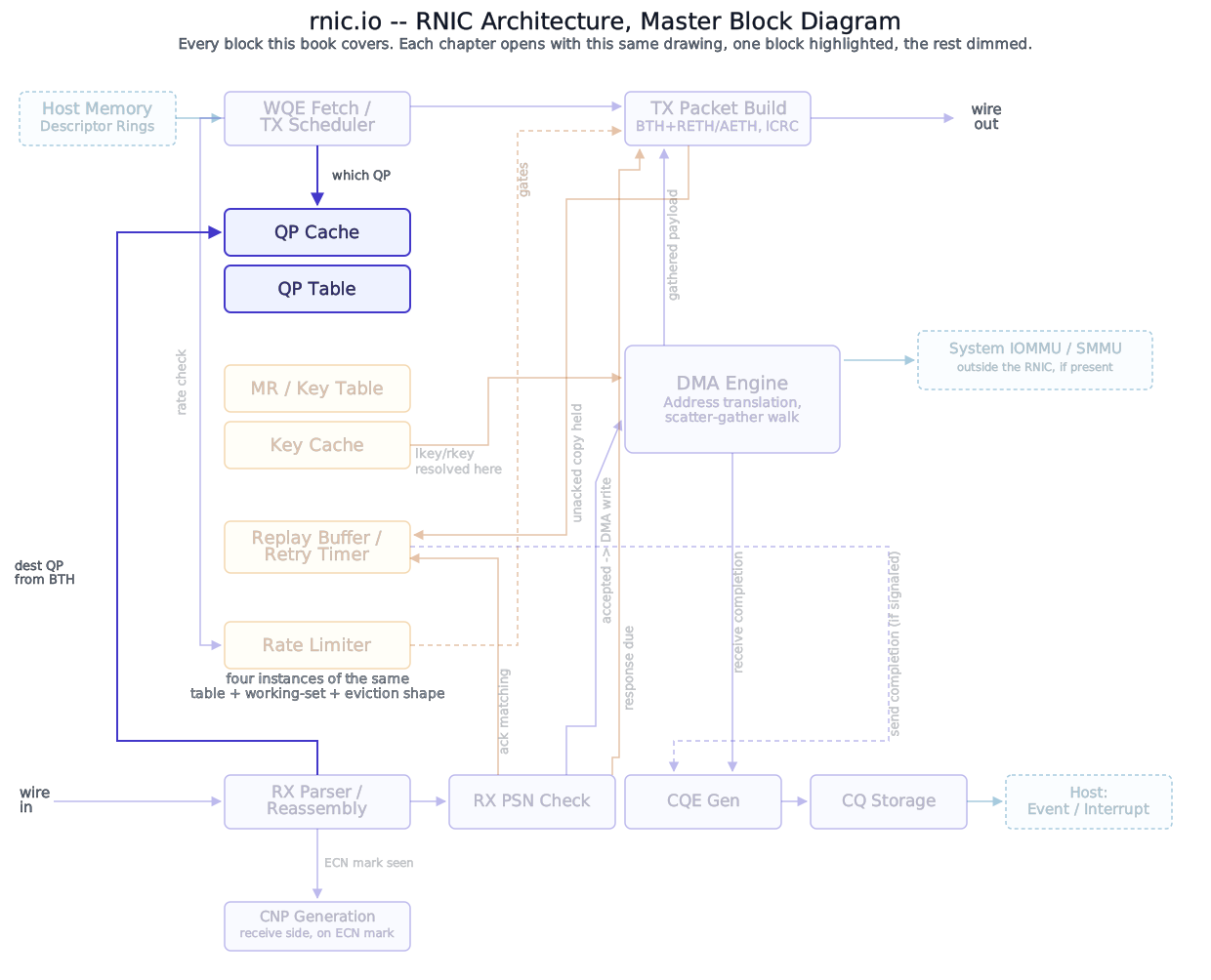
Every field below lives inside one entry of The QP Table, which the next chapter covers – this chapter is about what’s in that entry, not the structure holding it.
The fields, and what’s really two roles wearing one name
IBTA-V1 defines a Queue Pair’s context directly, as the complete attribute set a state transition can supply and hardware can act on – everything below is named for the architectural role it plays, not for any one software interface’s struct layout. Real hardware is free to pack, reorder, or split these fields however its own pipeline needs; nothing here asserts a specific silicon-side layout.
Two fields deserve pulling out before the full list: they’re the most commonly misread pair in this entire context.
- The requester-side outstanding-read/atomic ceiling – how many RDMA read and atomic requests this QP may have outstanding as the requester, at once. It bounds how deep this QP’s own send-side read/atomic pipeline can run.
- The responder-side outstanding-read/atomic ceiling – how many incoming RDMA read and atomic requests this QP will accept and hold as the responder, before it has to push back. It bounds how many of the remote peer’s read/atomic requests this QP can have in flight against it.
These are independently negotiated, apply to opposite directions of the same connection, and are very often asymmetric – a QP that mostly issues reads and rarely serves them might run a high requester-side ceiling and a low responder-side ceiling.
“Outstanding” means issued and unanswered, not merely queued – a distinction worth walking through with actual numbers. Say this QP’s requester-side ceiling is 4, and software posts eight READ WQEs back to back. Hardware issues the first four right away, as four separate READ REQUEST packets; each one occupies a slot until its READ RESPONSE data comes back from the remote peer. WQEs five through eight sit fully formed and ready in the Send Queue, but hardware doesn’t touch them yet – issuing a fifth would mean tracking five in-flight responses against a ceiling of four. The moment WQE #1’s response arrives and that read completes, its slot frees up, and hardware issues WQE #5. Two things are bounded here, and they’re not the same thing: the ceiling bounds how many reads can be in flight at once (four), while the Send Queue’s own depth – a separate resource, covered in The Send Queue Ring – bounds how many WQEs can be queued up waiting their turn behind it.
Concept
Requester-side ceiling = what this QP has sent (bounds its own read/atomic pipeline). Responder-side ceiling = what this QP will accept (bounds the peer’s read/atomic requests against it). Same shape, opposite direction, independently sized.
Gotcha
Reading one where the other belongs is the single easiest way to misdiagnose a QP context. Getting it backwards doesn’t fail loudly – it silently under- or over-provisions one direction of a connection until traffic patterns expose it.
Beyond that pair, the fields split cleanly by transport scope. UD (Unreliable Datagram) has no remote-access permission concept at all – it supports only SEND/RECEIVE, so the remote-access permission mask doesn’t apply to it either, alongside the rest of RC/UC’s connection-oriented fields below. RC (Reliable Connection) carries every field UC does plus the ones only a connection with hardware-managed reliability needs: the ACK timeout, the retry-count ceiling, the RNR-retry ceiling, the RNR-NAK timer floor, and the outstanding-read/atomic ceiling pair above. UD (Unreliable Datagram) carries none of that – no reliability state to speak of, no destination-QP field even, since a UD QP names its destination per-message rather than once at connection setup. UC (Unreliable Connected) sits between the two: connected like RC, but without the reliability fields, since there’s no retry engine reading them. (A fourth transport, XRC, decouples a QP’s receive side from any one specific send-side QP, to cut per-peer QP count in large fan-in deployments – it’s out of scope here; this part assumes RC throughout.)
Block diagram
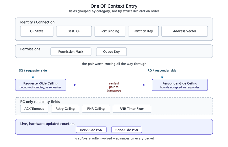
This chapter’s one diagram earns its place on exactly the pair the prose above spends its first section on: the requester-side and responder-side outstanding-read/atomic ceilings drawn with their directions made explicit, since the two fields differing only in which side of the connection is counted is precisely what makes them easy to transpose.
Set once, or updated by hardware on every packet
Most of a QP context is written by software once, at a specific state transition, and then held fixed by hardware until the next explicit write: the path MTU attribute, the destination-QP field, the address vectors, the partition-key index attribute, both outstanding-read/atomic ceilings, the RNR-NAK timer floor, the ACK timeout, the retry-count ceiling, the RNR-retry ceiling, the port-binding attribute, and (UD-only) the queue key. Installing a QP and QP State Machine cover exactly which fields each transition requires and why hardware refuses the transition without them. The remote-access permission mask is a third case, distinct from either bucket: it must first be supplied at RESET→INIT like the fields above, but – unlike the port-binding or partition-key attributes – it isn’t frozen there for the QP’s whole life. Installing a QP covers the live, same-state path that re-opens it later.
A smaller set moves continuously, under hardware’s own control, with no software write involved at all: the receive-side PSN counter (the next PSN this QP’s receive side expects, advancing on each in-order accepted packet) and the send-side PSN counter (the next PSN this QP’s send side will stamp on a new message, advancing on each one sent). A live count of outstanding requester- and responder-side read/atomic operations is tracked against the two ceilings above, but IBTA-V1 defines only the ceiling as an addressable attribute, not the running counter – how a given implementation names or organizes that counter internally isn’t something this book states as fact. A send-queue-draining status bit is a third, narrower case: hardware sets it, software only ever reads it.
Deep walkthrough: three fields, traced end to end
Not every field named above gets the same full treatment here, and here’s why. The port-binding attribute, the partition-key index attribute, and the remote-access permission mask already get real depth in Installing a QP – what each one gates, what happens if it’s missing, and (for the permission mask specifically) the one live path that reopens it later – so this chapter doesn’t re-derive that story. The ACK timeout, the retry-count ceiling, the RNR-retry ceiling, and the RNR-NAK timer floor belong to the reliability engine’s own retry/timeout machinery, which this book hasn’t reached yet (Reliability Engine); naming them here as fields this QP carries is as far as this chapter goes. The path MTU attribute and the queue key (UD-only, and this part assumes RC throughout) don’t get dedicated depth anywhere in this book’s current scope. The three fields below are the ones whose story belongs specifically to this chapter – not owned by a single transition, and not deferred to a part that doesn’t exist yet.
The responder-side outstanding-read/atomic ceiling – the responder-side ceiling from above.
- What: an 8-bit value, RC only, set once at the INIT→RTR transition.
- Where this is checked: at the responder, against a live count of that QP’s currently outstanding incoming read/atomic requests, whenever a new
RDMA_READ_REQUESTor atomic opcode arrives for it. - When it fails: a request that would push the live count past this ceiling isn’t treated as a transient, retry-and-move-on condition – it’s classified as a QP access error (the same event class that covers an
rkeyviolation), and it forces the QP straight to the ERROR state. - What happens next: Single-QP Error Handling owns everything downstream of that – what “forced to ERROR” actually does to outstanding work on both queues.
The destination-QP field – the peer’s QP number, RC/UC only, set once at INIT→RTR, held fixed for the connection’s life.
- What: a 32-bit field holding the 24-bit destination QP number – the exact width and position What Is RoCEv2 already described inside the BTH.
- Where this is used: not checked against an incoming packet so much as stamped into every outgoing one – the TX pipeline (TX Pipeline) builds each packet’s BTH by copying this QP’s destination-QP field straight into the destination-QP field of the header, on every single packet this QP ever sends.
- When it’s wrong: it isn’t something that can fail at runtime – it’s fixed at INIT→RTR and only reachable again through a full RESET. A QP simply cannot send to a different peer without being torn down and rebuilt.
- What happens next: nothing to retry here; this field’s only failure mode is a software bug at connection setup, not a hardware fault.
The receive-side and send-side PSN counters.
- What: 32-bit fields each holding a 24-bit PSN, the width What Is RoCEv2 described inside the BTH; RC/UC only for the receive-side counter, all transports for the send-side counter. The receive-side counter starts at a value software supplies at INIT→RTR (the PSN the peer’s first packet is expected to carry); the send-side counter starts at a value software supplies at RTR→RTS, then advances under hardware’s own control from there.
- Where this is checked: at the receiving QP, comparing the receive-side counter against the PSN carried in every arriving packet’s BTH – exactly which pipeline stage performs that comparison, and what happens to a packet that doesn’t match, is the RX pipeline’s (RX Pipeline) open question, deliberately not resolved here (see One Transaction, Start to Finish for the walkthrough that first flags it).
- What happens next: a PSN mismatch is reliability-engine (Reliability Engine) territory – this chapter’s job stops at naming the field and what it holds, not how a gap or duplicate gets handled.
Why
Splitting the outstanding-read/atomic ceiling into two independent fields, one per direction, rather than one shared “outstanding read/atomic” limit, is what lets a connection be asymmetric on purpose – a storage target that mostly serves reads and rarely issues them can advertise a generous responder-side ceiling and a minimal requester-side ceiling, sized to its actual role, instead of both ends negotiating down to the more conservative of two roles neither of them is symmetrically playing.
The QP Table picks this context up as a single addressable entry and covers where it actually lives.
References
- InfiniBand Trade Association, InfiniBand™ Architecture Specification, Volume 1 (General Specifications).