QP Capacity and Timing
Overview
The QP Table named a hard ceiling on QP count and moved on; QP Caching named a second, much smaller ceiling on how many QPs stay cheap to touch at once and moved on too. Neither chapter asked which ceiling is the one that actually matters, or why a real chip publishes the specific maximum-QP number it does. This closing chapter asks both questions – what really sets a QP count ceiling, across every resource a QP consumes, not just this table – and then asks a second, related question this part has left completely unopened: how a slow, infrequent software write and a fast, constant per-packet read end up touching the exact same structure safely.
Locator
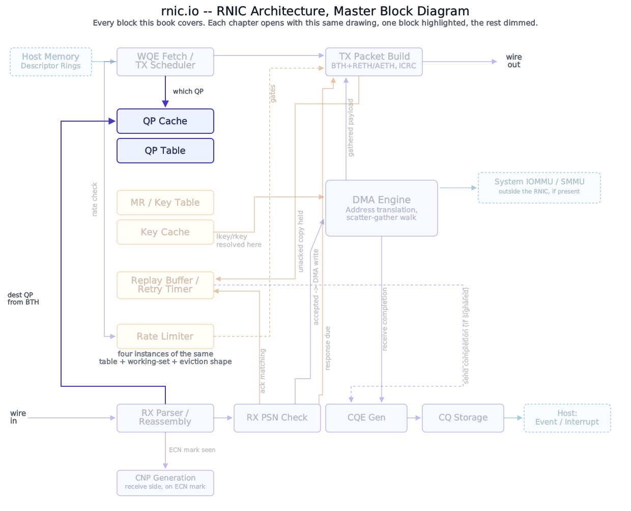
Block diagram
Deep walkthrough
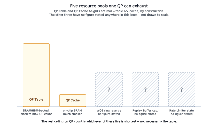
Two different kinds of ceiling, and only one of them is real. The QP Table is sized to hold every QP the adapter allows to exist at once; a creation request past that limit fails outright. QP Caching’s on-chip working set is much smaller than that, and a QP falling outside it doesn’t fail anything – it just costs a round trip back to the table on the next touch. These are not the same kind of limit. A full table is an existence failure: the QP was never allowed to be born. A cache miss is a performance cost paid by a QP that already exists and is doing real work. Conflating the two – “the cache is small, so the chip must only support a few thousand QPs” – gets the architecture backward: the cache bounds how many QPs stay cheap, not how many can exist.
Gotcha
A bigger QP Table doesn’t automatically buy a bigger maximum-QP number. If any other resource a QP consumes at creation time – a WQE ring reservation, a Replay Buffer allocation, a Rate Limiter table entry – is provisioned for fewer QPs than the table itself, growing the table alone changes nothing. The real ceiling is the smallest of every hard, per-QP-existence resource a chip builds, and that is a design consideration left to the architect.
What actually sets the real ceiling. A QP’s existence isn’t just one table entry. By the time a QP reaches RTS, it has a live claim on several resources this book names across several parts: a WQE ring reservation for its outstanding sends (TX Pipeline), a share of Replay Buffer capacity for whatever it has sent and not yet had acknowledged (Reliability Engine), and – once this book reaches it – a Rate Limiter table entry tracking its own injection rate. Every one of those is a resource some other part of this book owns, not this one, and every one of them is a candidate for being the actual bottleneck. A real chip’s published maximum-QP number is the minimum across all of them, and no vendor documents the individual number for each resource that went into that minimum – what’s citable here is the shape of the tradeoff, not a figure.
The one distinction worth drawing before this book can say anything more specific: some of these resources are pre-allocated per QP at creation time and held for that QP’s whole life – a hard cost, paid whether or not the QP is doing anything right now. Others are a shared, evictable working set consulted on demand – a soft cost, paid only under pressure, in degraded performance rather than a denied request. The QP Table is the first kind by definition, and the Replay Buffer turns out to be both at once: Replay Buffer Caching puts its on-chip working set in the same shared, evictable SRAM pool the QP Cache uses, while Replay Buffer Capacity and Backpressure treats its total logical capacity as a hard, per-QP quota enforced by admission control instead – eviction isn’t survivable there the way it is for a cache entry with a backing copy still sitting in the QP Table. Whether a real Rate Limiter table follows either shape isn’t something this book can state as fact before Congestion Control Engine exists – but it’s the question worth asking of it when it does.
Why
A per-QP retry timer is the clearest case of this choice actually mattering. A dedicated hardware timer for every live QP is the simplest thing to reason about and the worst thing to scale – the timer count grows linearly with QP count, in a resource (timer/counter logic) that’s expensive per instance. The far more plausible real design is a shared timer-wheel or periodic-sweep structure: one piece of hardware that walks live per-QP deadline timestamps – timestamps that already live in QP Context regardless – on a fixed schedule, checking many QPs against one clock rather than running one clock per QP. This book has no public source confirming any specific vendor builds it this way; it’s reasoned from what scales, in the same spirit The QP Table’s flat-vs-multi-level reasoning is.
Where this is checked, and why it mostly isn’t – until it is. Nothing about capacity is checked per packet. It’s checked exactly once, at QP creation, against whichever resource happens to be exhausted first, and the software-facing result is a failed allocation call – the same shape The QP Table already described for its own entries. The interesting question isn’t the check itself, which is unremarkable; it’s that this book has now named four different places that check could fail – the QP Table plus the three hard resources named above – owned by four different parts, and no single one of them can be inspected in isolation to answer “how many QPs can this chip actually run.” The QP Cache sits outside that count entirely, for the reason the previous section just drew out: it has no failure mode at creation time to add to the tally.
A second question this part has left completely open: timing. Nothing this part has covered yet has asked how fast any of this actually runs, or what clock a QP Table lookup runs on relative to the software call that created the QP in the first place. Those are two very different kinds of access to the same structure, and they don’t share a clock domain by default.
Two write paths, two very different tolerances for delay. A QP’s live state gets touched from two directions that have almost nothing in common. The datapath direction is frequent and unforgiving: a send updates this QP’s send-side PSN, a receive advances its receive-side PSN (QP Context), on close to every packet, and that update has to complete in the same handful of cycles as the rest of a per-packet pipeline stage – it runs entirely inside whatever clock domain the core packet-processing datapath itself runs on, with no domain crossing involved at all. The control-plane direction is the opposite: a modify-QP request – a state transition, an attribute change – arrives rarely, tolerates real latency without anyone noticing, and almost certainly arrives over a register or command interface clocked independently of the datapath, likely tied to whatever clock the host-facing interface itself runs on. That register write and the datapath’s own PSN updates are touching the same QP Cache entry from two different clock domains, and that’s a real clock-domain crossing (CDC) – not a hypothetical one.
Analogy
A CPU’s architectural register file is fast because it lives in the same clock domain as the pipeline reading and writing it every cycle. A context switch – an OS-driven event, not a per-instruction one – has to land an entirely different set of register values into that same fast structure without ever stalling an in-flight instruction on some other thread. A QP’s live PSN counters are that register file; a modify-QP call is a context switch happening to somebody else’s connection, arriving over a much slower path than the one the datapath itself runs on.
Why a synchronizer can never sit on the hot path. The standard way to move a single control bit safely across a clock-domain boundary is a two-flop synchronizer – and it’s the wrong tool here twice over. First, a modify-QP request carries a whole attribute struct, not one bit; a plain synchronizer only guarantees a clean value for a single signal, and sampling several unrelated bits through separate synchronizers gives no guarantee they were ever consistent with each other at the same instant. Multi-bit data crossing a clock domain needs a real handshake – a request/acknowledge protocol or a small asynchronous FIFO – not a flop pair. Second, and more importantly: whichever mechanism is used, it adds latency and (for a plain synchronizer) a small, real risk of metastability resolving late. Neither is acceptable anywhere near a per-packet lookup that has to return a hit or miss in a fixed, small number of cycles, every packet, without exception.
The way this actually gets built, almost certainly, is by keeping the crossing off the hot path entirely rather than trying to make it fast enough to belong there. A modify-QP request lands in a small staging structure – a shadow copy of the entry, or a shallow command queue – on the control-plane side of the boundary, crosses through a proper handshake, and only gets applied into the live QP Cache entry the datapath actually reads at a moment the datapath itself isn’t mid-lookup against that same entry. The datapath’s own reads and its own PSN writes never wait on anything crossing a clock domain; only the comparatively rare control-plane update does.
Food for Thought
If a real implementation could only afford to build one of these five per-QP resources as a true hard-allocated, per-QP-dedicated structure – and had to make every other one a shared, evictable working set instead, accepting graceful slowdown under pressure rather than a hard ceiling – which one would you pick, and why? What breaks if you get it wrong?
Pipeline depth, briefly. None of this implies a QP Cache lookup itself completes in a single cycle just because it stays inside one clock domain. A set-associative cache lookup is ordinarily a small multi-stage pipeline in its own right – something like an index/hash stage, a parallel tag-compare stage across ways, and a hit/miss-and-data stage – adding a few cycles of fixed latency before a TX scheduler or RX parser sees a result, not one. This book states that shape as reasoned inference about how a cache lookup like this one is ordinarily built, not as a specific vendor’s pipeline; the actual stage-by-stage behavior of the pipelines this lookup feeds into belongs to TX Pipeline and RX Pipeline, not here.
This chapter closes Queue Pair Management. Memory Region / Key Table is next.
References
- No IETF or IBTA standard governs per-QP resource capacity, silicon clocking, or pipeline staging – all of it is implementation-specific hardware design, not a wire-format or software-interface contract any standards body defines. This chapter’s capacity reasoning is grounded in the same architectural inference The QP Table and QP Caching already used, extended across resources those chapters don’t own.
- Clifford E. Cummings, “Clock Domain Crossing (CDC) Design & Verification Techniques Using SystemVerilog,” SNUG (Synopsys Users Group), Boston, 2008 – widely cited general CDC methodology (two-flop synchronizers for single-bit signals, handshake/FIFO techniques for multi-bit data), not an RNIC-specific source. This chapter applies that general methodology to a QP Table/Cache boundary; it isn’t claiming any real RNIC vendor builds it exactly this way.