The Rate Control State Machine
Overview
Rate-Limiter Context named the timer, byte counter, and their stage counts without saying what they were for. This chapter is what reads them: a real, three-phase state machine that decides, on every timer or byte-counter expiry, whether this QP’s current rate should leap toward its target, creep toward it, or ramp aggressively past the caution either of those two phases would otherwise apply.
Locator
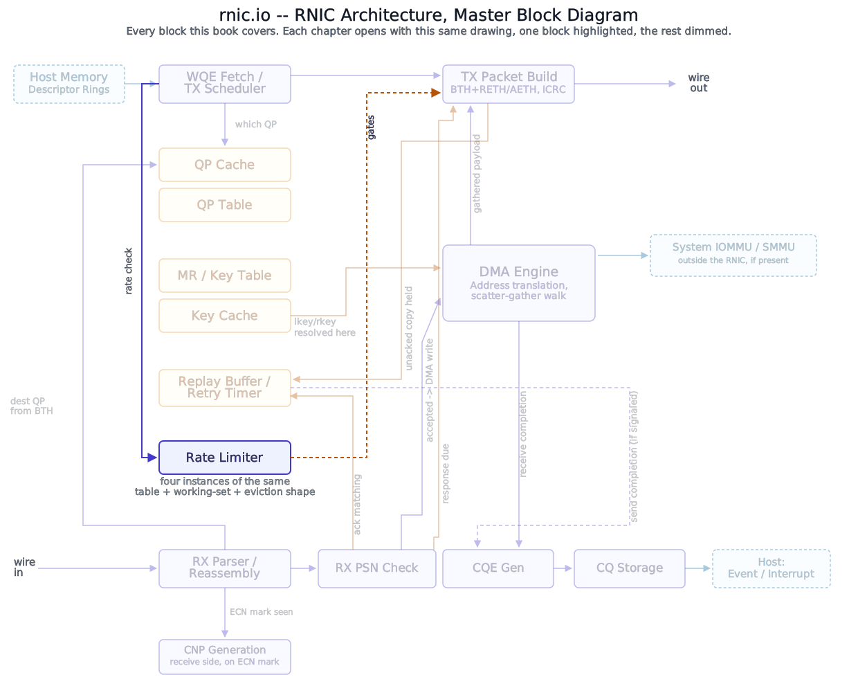
CNP Generation covered what triggers a rate cut. This chapter is what happens on every cycle after one – the machinery that decides how fast recovery actually proceeds.
Block diagram
All 14 steps
- The cut. A QP sending at 64 Gb/s. The numbers in this walk are illustrative: the reaction factor α is held at 0.5 and the phase threshold F is 3. Rate-Limiter Context
- A CNP arrives. The current rate is remembered as the target, then cut by α/2: 64 × 0.75 = 48. Both stage counts go to zero. In a real adapter α itself rises with CNPs and decays without them; it is held still here so the arithmetic stays visible, and the last scene shows it moving. CNP Generation
- Recovery. The rate timer fires, and advances only its own stage count. Rate-Limiter Context
- Fast recovery: both counts are still below F. The current rate jumps to the midpoint of itself and the target, (48 + 64) / 2 = 56. The Rate Control State Machine
- Three more firings, byte counter, timer, byte counter: each halves the remaining gap, 60, then 62, then 63. The target has not moved. The Rate Control State Machine
- No. The larger count is no longer below F, so this is additive increase: the target itself climbs a fixed step, 4 Gb/s here, and the current rate closes half the distance to it, (68 + 63) / 2 = 65.5. The Rate Control State Machine
- The timer fires and reaches 3 too. The smaller count is at F, not past it, so the QP stays in additive increase: target 72, current (72 + 65.5) / 2 = 68.75. The Rate Control State Machine
- Both counts pass F with no new CNP: Had both counters kept firing until the smaller passed F, hyper increase would take over and ramp harder than the fixed step. The algorithm defers that formula to another specification, so this walk shows no number for it. The Rate Control State Machine
- Cut again. Back to the top, whatever the phase: the target becomes 68.75, the current rate is cut to 68.75 × 0.75 ≈ 51.6, and both counts go to zero. Recovery starts over from fast recovery. CNP Generation
- How α trends. α was held at 0.5 above. In DCQCN it is updated once per fixed window: a window with a CNP moves it toward 1 by α = (1 − g)α + g, and a window without one decays it by α = (1 − g)α. The paper’s g is 1/256; this scene uses 1/4 so the trend shows in a few steps. Rate-Limiter Context
- A window with a CNP: α = 0.75 × 0.5 + 0.25 = 0.625. A cut now would keep 1 − α/2, about 69% of the rate. Rate-Limiter Context
- Another window with a CNP: α rises to about 0.72, and the next cut would keep only 64%. Sustained congestion makes each cut deeper. Rate-Limiter Context
- No. Each quiet window takes off a quarter: 0.54, 0.40, then 0.30. α remembers the recent trend instead of the last event. Rate-Limiter Context
- A CNP arriving now meets a low α and cuts gently, keeping 85% of the rate. The same CNP after the two congested windows would have kept 64%: the cut is sized by how congested the path has been lately. The Rate Control State Machine
Deep walkthrough
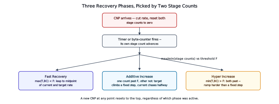
The reset: one event, two immediate effects. CNP Generation’s output is this chapter’s own trigger. The instant a CNP arrives for this QP, two things happen at once, sourced directly from the algorithm this Part has used throughout: the current rate is cut – remembered as the new target, then reduced by an amount the reaction factor scales – and both the timer’s and the byte counter’s own stage counts reset to zero. Everything from this chapter onward describes what happens in the absence of another CNP, starting fresh from that reset point.
Gotcha
The reaction factor scaling the cut, and the stage counts driving recovery afterward, are two different pieces of state answering two different questions. One decides how hard this cut lands; the other decides how the climb back proceeds. A QP that’s been cut hard and a QP that’s been cut gently run through the exact same three recovery phases below – the reaction factor doesn’t pick a different recovery path, only a different starting point on the same one.
Two independent triggers, two independent stage counts. Rate-Limiter Context already named the asymmetry worth repeating here: a timer and a byte counter both run at once, and either firing advances only its own stage count, on its own schedule. A QP sending a high rate of small messages can advance its byte-counter stage well ahead of its timer-based stage; the reverse holds for a QP sending large, infrequent bursts. Neither stage count on its own decides anything – it’s the comparison between them, described next, that actually selects a phase.
Phase one: fast recovery. While the larger of the two stage counts is still below a fixed threshold – meaning both counts are still low, since neither trigger has fired many times yet – the current rate leaps directly toward the target: each expiry sets the current rate to the midpoint between itself and the target, roughly halving the remaining distance every step. One documented deployment fixes this threshold at five steps; a second, independent implementation defaults to three – the same evidence this Part has already used elsewhere that these specific numbers are tuned parameters, not fixed constants.
Gotcha
This is checked against the larger stage count, not the smaller one – both counts have to still be low for fast recovery to apply. A QP sending small messages fast can advance its byte-counter stage well past the threshold while its timer-based stage is still low; checking only the smaller count would keep that QP in fast recovery based on the trigger that’s barely fired, ignoring the one that’s already fired many times. The state machine cares whether either trigger has accumulated enough firings to signal the burst is over, not whether both have.
Phase two: additive increase. Once one stage count has crossed the threshold but the other hasn’t – exactly the straddling case the Gotcha above describes – the climb changes character: instead of chasing an already-fixed target, the target itself starts climbing, by a fixed step each cycle, with the current rate continuing to close half the distance to it. This is the steady-state phase – slower, more cautious, and where a QP spends most of its time recovering after the initial fast-recovery burst has closed most of the gap.
Why
Two phases, not one, because the two halves of recovery have opposite priorities. Immediately after a cut, the current rate is likely still far below what the link can actually sustain – fast recovery’s job is closing that gap quickly, accepting a coarser step size because there’s a lot of ground to cover and low risk of overshooting a target that hasn’t moved. Once the current rate is already close to the target, the same coarse step size would risk oscillating past a ceiling the network only just confirmed it could sustain – additive increase’s smaller, target-advancing steps trade recovery speed for stability once stability is the thing actually worth optimizing for.
Phase three: hyper increase. If both stage counts run well past the fast-recovery threshold with no new CNP arriving – a long enough stretch of apparently uncongested sending – a third, more aggressive phase engages, ramping harder than additive increase’s fixed step allows. The algorithm this book sources throughout this Part defers this phase’s own formula to a separate, underlying specification rather than restating it in full, and this book does the same rather than inventing one. What is documented directly: at least one real, named vendor found this phase, as originally specified, ineffective at actually delivering a fast ramp-up, and replaced it in shipped hardware with a different aggressive-increase scheme of their own – rate increase that doubles in magnitude with each further congestion-free period, precisely so a QP that’s been idle-of-congestion for a while reclaims its full share of bandwidth quickly rather than crawling back at additive increase’s steady, deliberately-cautious pace.
Analogy
Three phases picked automatically by a threshold comparison is the same shape Single-QP Error Handling’s own fault-classification logic uses – a QP doesn’t choose which recovery behavior applies, the state it’s already in does. Here, the state is a pair of counters advancing since the last CNP; there, it’s a specific fault condition. Neither is a decision this book’s own reasoning makes on a chapter’s behalf.
Where this connects. Every phase above only ever runs in the absence of a new CNP – CNP Generation’s own mechanism can interrupt this state machine at any point, cutting the rate and resetting both stage counts regardless of which phase was active. What happens if this QP’s rate-limiter context itself faults or holds a corrupted value mid-cycle is Single-QP Rate-State Faults, next.
Interface reference
| Phase | Trigger condition | Effect | Source |
|---|---|---|---|
| Rate cut | CNP arrives | current rate cut, scaled by reaction factor; both stage counts reset to 0 | DCQCN paper |
| Fast recovery | larger stage count still below threshold F (both counts low) | current rate set to midpoint of itself and target | DCQCN paper (F=5); a second, independent implementation defaults to 3 |
| Additive increase | one stage count past F, the other not yet, no new CNP | target rate climbs by a fixed step; current rate closes half the remaining distance | DCQCN paper |
| Hyper increase | smaller stage count also past F (both counts past it), no new CNP for an extended period | an aggressive ramp beyond additive increase’s fixed step | formula deferred to an underlying spec by the sourced algorithm itself; at least one real vendor replaced this phase entirely in shipped hardware |
References
- Zhu, Eran, Firestone, Guo, Lipshteyn, Liron, Padhye, Raindel, Haj Yahia, Zhang, “Congestion Control for Large-Scale RDMA Deployments,” SIGCOMM 2015 – the full rate-cut equations, the fast-recovery/additive-increase formulas, and the three-phase state machine (their own Figure 7), including the
F=5 default and the hyper-increase phase’s deferral to QCN’s own specification. - Voloshin, “Introduction to Congestion Control for RoCE,” Broadcom white paper NCC-WP103 (2023) – a second, independent, real implementation confirming the same three-phase shape under its own defaults (three fast-recovery steps, not five) and documenting its own replacement for the hyper-increase phase.