Rate-Limiter Context
One Transaction, Start to Finish already named this chapter’s subject in passing: before the adapter spends any further effort on a WQE, “the rate limiter decides whether this QP’s turn to dispatch a packet has actually come, pacing when a WQE proceeds.” This is where that decision’s own state actually gets defined, field by field.
Overview
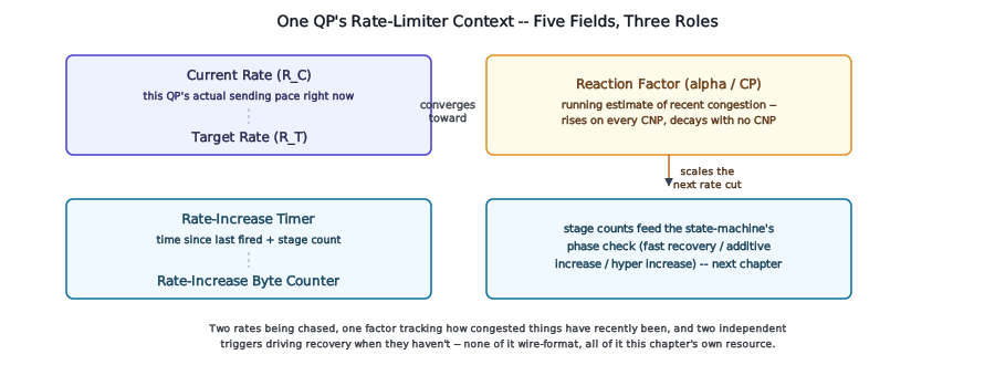
A rate limiter’s per-QP context is small compared to everything else this book has named so far, but it isn’t one number. It’s a current sending rate and a separately-tracked target rate the current one is always chasing, a single factor that decides how far the current rate gets cut the next time congestion is reported, and the timer-and-counter pair that claws the current rate back up when it isn’t. None of these five fields has a wire-format home – RoCEv2 defines the packet that reports congestion and nothing about how a NIC reacts to it, so every field below is this chapter’s own resource, not a spec-mandated structure.
Concept
Every other per-QP context this book has covered so far describes a connection’s identity or its delivery state – who it’s talking to, what it’s acknowledged, what’s still in flight. Rate-limiter context describes neither. It’s the QP’s own memory of how congested the network has recently been, and how it’s currently responding to that memory.
Locator
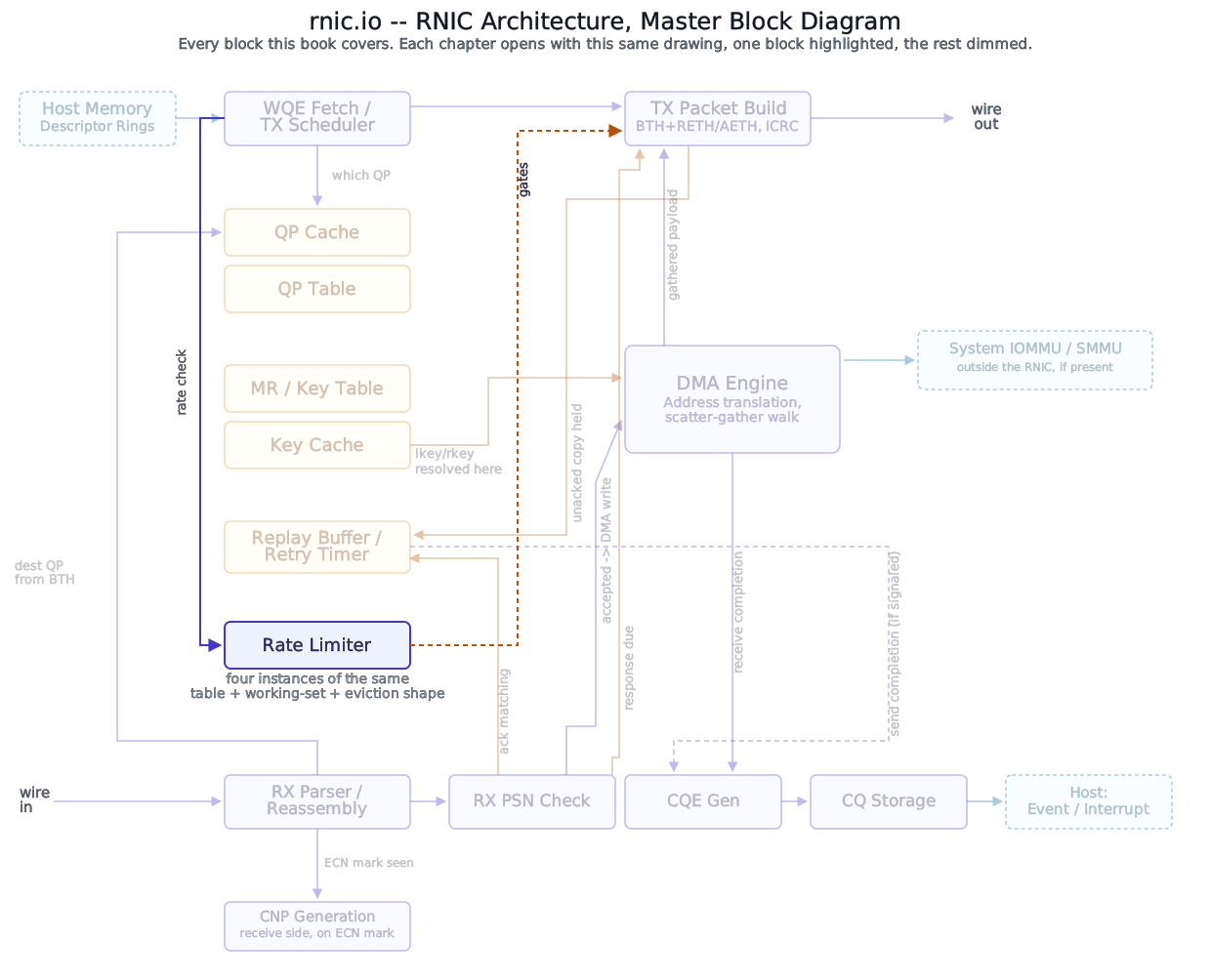
Every field below lives inside one QP’s own entry in the Rate Limiter – the storage structure the next chapter in this Part covers. This chapter is about what’s in that entry, not the table holding it.
Block diagram
Deep walkthrough
What the standard leaves unspecified, stated by the standard itself rather than inferred. RoCEv2 defines the mechanism for marking a packet as congestion-experienced and the format of the Congestion Notification Packet (CNP) that reports it – both wire-level facts the next chapter covers in depth. It says nothing else. A vendor’s own public documentation of RoCEv2’s scope states this directly: the standard “leaves the particular congestion control algorithm unspecified, including… when CNPs are generated in response to ECN [and] how sending rate is adjusted in response to CNPs.” Every field this chapter names is that unspecified algorithm’s own state, not a structure RoCEv2 requires any NIC to keep.
The two rates, and why a rate limiter needs both instead of one. A QP’s current rate is the pace it’s actually sending at right now. Its target rate is a separately-remembered value the current rate is always converging toward, set once at the moment a Congestion Notification Packet arrives and left alone until the next one does. Splitting these into two fields, rather than tracking one rate and a raw “increase or decrease” instruction, is what lets the recovery mechanism below converge on a specific value quickly rather than groping toward an unknown one step at a time.
Why
Remembering a target the instant a CNP arrives means the rate-recovery mechanism has a real number to aim at from the very first recovery step, not just a direction. The alternative – incrementing the current rate by a fixed amount each step with no target in mind – either overshoots a network that’s still congested or takes far longer to reclaim bandwidth a network that’s already recovered can actually give back. A remembered target lets recovery be fast where it’s safe and cautious where it isn’t, instead of picking one behavior for both cases.
The reaction factor, and what it actually remembers. A single field – called α (alpha) in the algorithm this book sources below, CP (“congestion probability”) in a second, independent implementation’s own documentation – tracks a running estimate of how much of this QP’s recent traffic has been running into congestion, not merely whether the most recent packet did. Every Congestion Notification Packet nudges this factor up; a stretch of time with no CNP at all nudges it back down. The current rate’s next cut, when a CNP does arrive, is scaled by this factor directly: a QP that’s seen sustained, heavy congestion gets cut hard, one that’s seen a single isolated signal gets cut gently.
Analogy
This is the same shape Reliability Engine’s retry-and-timeout state already uses for a different problem: a single piece of memory summarizing how bad has this been lately, updated incrementally rather than reset fresh on every event, so the response scales with a trend instead of overreacting to one data point.
The rate-increase mechanism’s own tracking state – a timer, a byte counter, and how far each has run since the last cut. In the absence of a new CNP, the current rate is allowed to climb back toward the target, and two independent triggers drive that climb: a fixed amount of time passing, and a fixed number of bytes having gone out. Each trigger carries its own live counter (how much time or how many bytes since it last fired) and its own stage count (how many times it has fired since the current rate was last cut). Those two stage counts, compared against a fixed threshold, are what the state-machine chapter later in this Part uses to decide which of that mechanism’s several recovery phases applies right now – this chapter’s job is only naming that the tracking state for that decision exists and lives here, not walking through the phases themselves.
Gotcha
Don’t read “timer” and “byte counter” as two names for the same thing measured differently. Both run at once, independently, and either one firing advances that trigger’s own stage count on its own schedule – a QP that’s sending a high rate of small messages can advance its byte-counter stage well before its timer-based stage catches up, and the reverse holds for a QP sending rarely but in large bursts. The state machine that consumes both stage counts, not this chapter, is where that interaction actually matters.
Where this connects. Every field above belongs to one QP, addressed the same way the next chapter covers in full. What actually triggers a rate cut – a Congestion Notification Packet arriving – and what the wire format of that packet actually is belong to CNP Generation, fed from the receive side of a connection this QP shares with its peer. What decides whether this on-chip context is even resident when a WQE needs it is Caching, later in this Part.
Interface reference
| Field | Carries | Standard’s role |
|---|---|---|
| Current rate | this QP’s actual sending pace right now | architect’s choice – RoCEv2 specifies no rate-adjustment mechanism at all |
| Target rate | the rate the current one is converging toward, set when the last CNP arrived | architect’s choice |
Reaction factor (α) | a running estimate of how congested this QP’s recent traffic has been | architect’s choice – named α in one public algorithm, CP in a second, independent implementation’s own documentation |
| Rate-increase timer + stage count | time-based trigger for climbing the current rate back toward the target, and how many times it has fired since the last cut | architect’s choice |
| Rate-increase byte counter + stage count | byte-based trigger for the same climb, and how many times it has fired since the last cut | architect’s choice |
References
- InfiniBand Trade Association, Supplement to InfiniBand Architecture Specification Volume 1, Release 1.2.1, Annex A17: RoCEv2 (2014) – governs the Congestion Notification Packet’s wire format, covered in CNP Generation; says nothing about the fields on this page.
- Zhu, Eran, Firestone, Guo, Lipshteyn, Liron, Padhye, Raindel, Haj Yahia, Zhang, “Congestion Control for Large-Scale RDMA Deployments,” SIGCOMM 2015 – names the current-rate/target-rate/alpha state and the timer-plus-byte-counter recovery mechanism directly (their own notation:
R_C,R_T,α). - Voloshin, “Introduction to Congestion Control for RoCE,” Broadcom white paper NCC-WP103 (2023) – a second, independent, real implementation’s documentation, confirming the same state and mechanism under different variable names (
CPin place ofα) and different default parameters, cited directly rather than assumed to match.